Monday, November 18. 2013Storm Damage 11-17-13Sunday November 17, 2013 about 11:50 AM a severe storm hit the area. 6 poles were broken at the ground by strong winds. All the broken poles are between the bridge and Karstens crossing. Max Tyms and Roger Smessaert will begin repairs today.  view West from karstons  view West from karstons Monday, March 4. 2013Winter work in the line department
There's always something to do. Outside work on the yards project has slowed to a crawl but the parts that came down in the fall are ready to go up in the spring. It's nice and warm inside the B&G Building, no wind eather. A good place to recondition parts for the yards and build up stock.
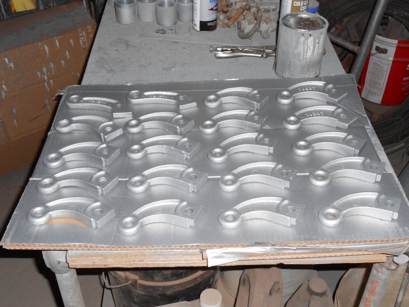 Newly reconditioned parts 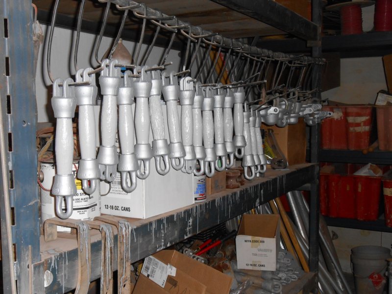 Another batch of woodstrains I fixed up the media blaster with a new air supply hose from the compressor. The 75 foot run was too much for the 3/8" air hose. Too much pressure loss. I doubled the size to 3/4" and that works Great! Now I can actually adjust the pressure at the blaster's regulator. It now makes quick work of rusty woodstrains. A new window and supply of window film means I could see what I'm blasting. When the weather is tolerable I work on accessible outside projects. 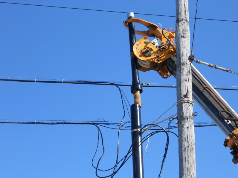 Setting steel pole extension. Work continues on moving equipment to the steel pole from the rotted wood pole by the pavilion. I set the pole extension and transferred the signal and phone cables. I finally got power into the second ART TRAIN car. That initiated a new project. Replacing the old transformers by the office which are now overloaded by the addition of the 2nd ART TRAIN car and additional lighting in the car shop. In order to facilitate that future transformer replacement without an extended power outage, I need to install a secondary tie between two transformer banks. This tie will also serve as an emergency backup in the event of a transformer failure involving the office or diner annex. I had planned such a tie for years but now it's installation is necessary. 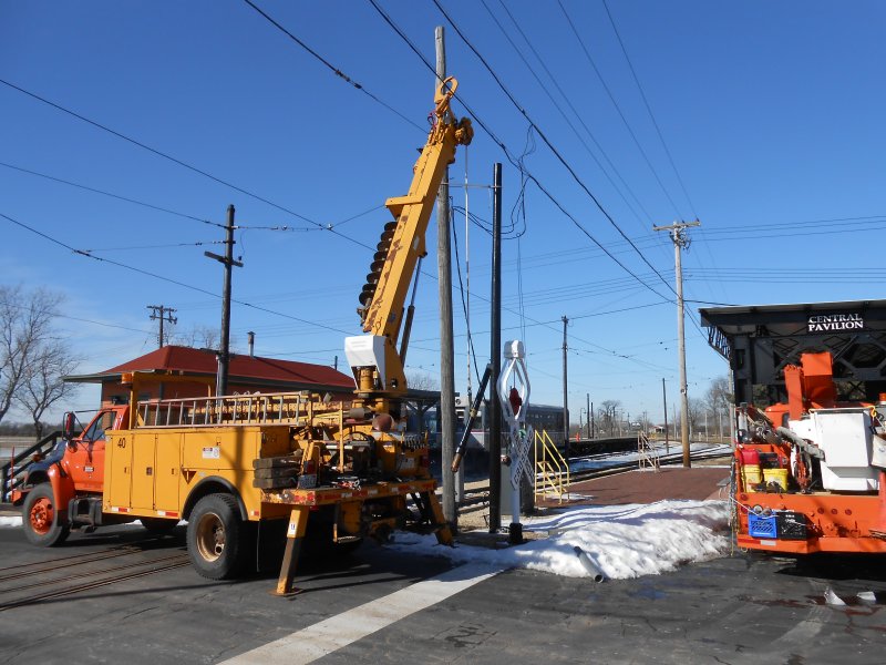 Transferring equipment to new steel pole. Other winter work involves getting ready to do other projects. Like a new display sign near the admission booth. I want to get the platform lights on 50th ave station working this year. These will be D/C cluster lights operating off the 600v railroad traction power but with new wire. Circuits will be rewired to a safety switch on a pole outside. The old open blade 600volt fuse box will remain undisturbed as a display but will be disconnected and not functional for obvious safety reasons. There are issues with the R33 rectifier which must be repaired when the weather warms. Spring maintenance must be done on the railroad, there are several broken insulator pins and dozens of catenary hangers to replace. Jole Ahrendt (car dept.) has been busy fabricating replacement catenary hangers. I understand these are ready waiting for a warmer day.
Tuesday, January 22. 2013Preventing lightning damageLightning protection is a very important aspect of an overhead traction power system. Substantial damage can occur without such protection. To avoid such damage lighting arrestors are installed at regular intervals. Arrestors are like a pressure relief valve for electricity. If the voltage (pressure) gets too high, the arrestor drains current to ground. Most damage caused by lightning is the result of it seeking a path to ground. The severe damage is the result of normal power current following the path the lightning surge created. 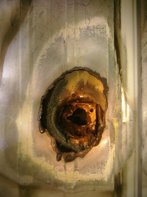 Hole through wall of barn 8 behind traction power disconnect caused by lightning and subsiquent power arc. 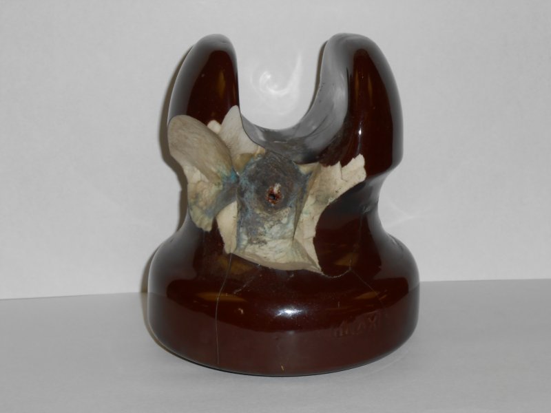 Feeder insulator punctured by lighting 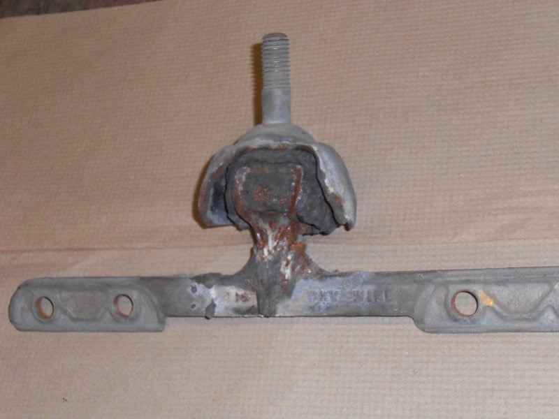 AGC hanger damaged by lightning induced power arc. At IRM I use metal oxide varistar (MOV) arrestors on both the A/C and D/C systems. These provide State-of-the-art protection. The arrestors are rated for the application voltage 175 Vac, 3KV ac, 1KVdc etc. All MOV arrestors function the same way. In this story we will deal with D/C arrestors. The MOV material conducts current at high voltage and has a high insulating value at low voltage. This "discharge" voltage is dependent upon the thickness of the MOV material. The thicker the material the higher the discharge voltage. When a surge exceeding the maximum continuous operating voltage (MCOV) rating reaches the arrestor the MOV material (valve) becomes conductive and discharges the surge to ground. As soon as the surge is gone and the voltage returns to normal the valve seals and becomes insulating again. 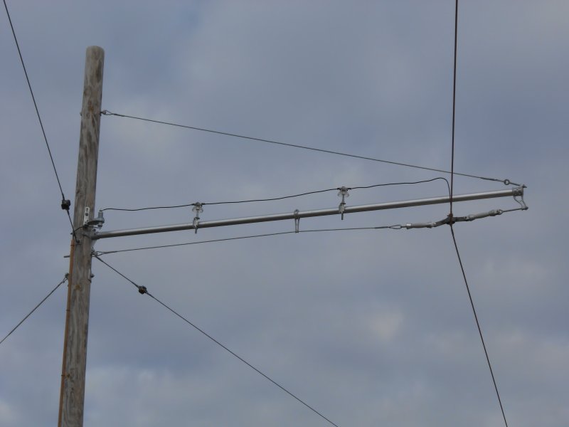 1KV D/C lightning arrestor installed on bracket arm pole. Note use of glass insulators mounted to bracket arm to support arrestor tap. 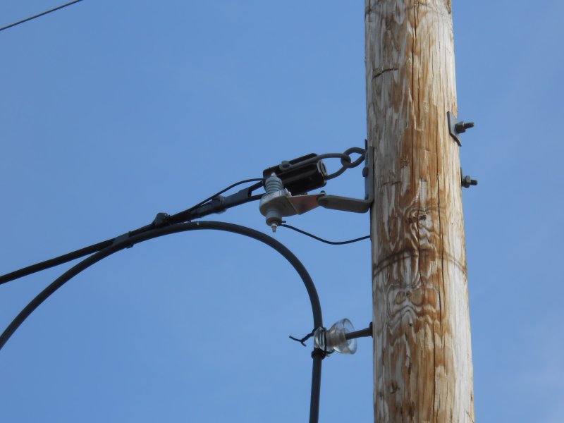 1KV D/C lightning arrestor protecting pit lead feeder. The most important part of an arrestor installation is the grounding. Grounding is simply a connection to the earth. The ground connection must provide a low resistance connection to the earth. There are many methods to accomplish this. A cable or plate can be buried or rods can be driven. Through experimentation, I have determined that four 5/8 inch by eight foot copper clad ground rods coupled together and driven to a depth of 32 feet, work best in our soil. This type of installation consistently provides a resistance of 13 ohms or less. Driving more rods to increase the depth did not lower the resistance enough to justify the effort. 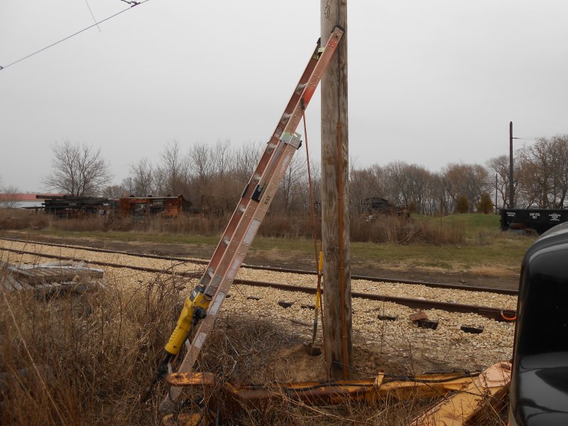 Setup for driving ground rods. To drive 32 feet of ground rod I use an electric pavement breaker with a special tool bit for driving ground rods. The breaker is light enough so it can be thrown on my shoulder and carried up a ladder then placed on the ground rod. A hardened steel cap is placed on the rod to prevent "mushrooming" the end. The rod is driven, then the next rod is placed in position. The rods are connected together using a threadless coupling. The hole in the coupling is tapered so that they are wedged together tightly when pounded into the ground. 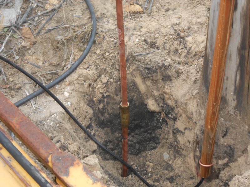 View showing threadless rod coupling. Note use of wood ground wire moulding. A #4 solid covered copper wire is used to connect the arrestor to the ground rod. The connection at the rod is made with a special clamp called an "acorn". It has a special "torque head" bolt. The head of the bolt is designed break or shear off when tightened to a predetermined torque value. This ensures a tight tamper resistant connection. The ground wire is covered with wood molding. This protects the wire from damage and protects both linemen working on the pole and people on the ground from contacting the ground wire. 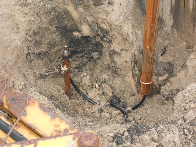 groundwire connected to rod with acorn type connector. Head of bolt breaks off when proper torque is reached.
|
Blog AdministrationCalendar
QuicksearchArchivesSyndicate This Blog |
|||||||||||||||||||||||||||||||||||||||||||||||||

Comments
Fri, 03-29-2024 21:26
We're slackers and spend more time working on the equipment in the shop than keeping all you readers updated. We'll work on it, but I'm sure updates [...]
Thu, 03-14-2024 08:02
What happened to the Department Blog? It's been over 2 years and I still regularly check for updates, but nothing comes...
Mon, 12-27-2021 16:28
Happy New Year to all the Departments at the Illinois railway Museum! Thanks for all the good work you do in railroad preservation. Ted Miles, [...]
Wed, 10-13-2021 13:33
Was the CB&Q 1309 every transported to IRM?I’ve been reading old issues of Rail&Wire and the car was mentioned several times.
Mon, 06-07-2021 22:40
I was wondering if in the model layout display what scale would you guys be using and would you be displaying model train history as well? Just [...]
Wed, 06-02-2021 17:27
Nice to see 428's cab back on. Looking forward to when it is operable!
Tue, 06-01-2021 16:47
I hope the work will continue on the UP #428. Now that they are the museum's connection to the national railroad network; she would be very [...]
Sat, 04-17-2021 23:07
What is the status of 126, the Milwaukee Buffet car that is in S. Dakota? Any guess on when or if it will get to IRM?
Wed, 04-14-2021 21:09
Perhaps it is time to scrap the remains of the c, B & Q 7128 to make room for the Villa Real. Ted miles, IRM member
Wed, 04-14-2021 15:26
Hi IRM my name is Jason and I was wonder If you guys would be willing to save a CN Dash8-40cm they are currently being retired by CN and being [...]
Fri, 04-09-2021 19:56
Bear in mind that the Nebraska Zephyr is an articulated train set, so cars cannot be inserted at will. Although cars and/or a second engine could be [...]
Wed, 03-31-2021 11:37
I believe Silver Pony is currently on the back burner, and has been put into storage in one of the barns. The car needs a lot of work done to it's [...]